Mini Lecture - A GLSL Tutorial in Practice
How does GLSL work, and how is it used?
Before we begin: Why learn GLSL?
There is an extensive collection of creative coding and audio/visual software available for learning how to create video art. Visualist/DJ Lime68k has listed over 55 on their vjing tools and resources list, and art mathematician Andrei Jay has a similar resource list (these are both amazing resources). There are also hardware video synths.
Do not try to learn everything all at once. It is important to balance exploration with application, balancing the learning of new tools with the practice and use of those skills. Time is our enemy, so we must be selective.
Here are the top outcomes I think you can achieve by learning GLSL as a tool:
- Create simple, light-weight, and customized visual OpenGL generators for web browsers, parallel processing, or low-performance devices such as a Raspberry Pi 1.
- Edit customized visual generators in real-time in a higher-level visual software such as TouchDesigner, Max/MSP, or Hydra.
- Create and use effects that do not exist yet in higher-level visual software, with the power of weird math.
Why use this tutorial?
Better tutorials exist. Below are three GLSL resources that helped me learn and inspired this tutorial. They cover the fundamentals in depth. This tutorial, however, serves as a practical example of how those fundamentals can come together to create a visual composition, step by step.
The Book of Shaders by Patricio Gonzalez Vivo & Jen Lowe.
If this is your first time seeing GLSL code, sections 00 to 03 will help answer: What is ‘GLSL’ and ‘Fragment Shaders’, and what is the code syntax. Sections 04-on have thoughtful visual explanations of common functions used to draw in GLSL.Inigo Quilez’s video and written computer graphics tutorials.
Inigo has many wonderful resources on 2D/3D GLSL rendering and elegant math code. A few of my favorites include: Learn to Paint with Mathematics, Coding the main bulb of the Mandelbrot set, and coding wavelet image compression (aka, part of .JPG compression)‘Shadertoy – unofficial’ tutorial blog posts.
Provides guidance to the quirks of Shadertoy as a compiler, as well as tips and tricks.
Goals for this GLSL code.
Before writing any code, I recommend outlining your visual and code goals. This helped to keep my exploration intentional and defined an end point.
- Create a hypnotizing spiral pattern.
- Use frame buffer feedback delay.
- Make the pattern colorful and nice (eye candy).
- Code runs in real time (< 17 ms, or > 60 FPS).
The Example: A Melting Interactive Spiral.
The end result is shown below. You can view it running live in Shadertoy here. However, I recommend you use “The Force” GLSL compiler by Shawn Lawson for learning and experimenting, as it live-compiles and has some small quality-of-life functions 2. I encourage you to follow along and copy the codes into The Force so you can experiment along the way.
GIF 0: End shader result. View the Shadertoy code here.
Step-by-step Walkthrough:
1) Create a blank screen.
We first must create a canvas to ‘draw’ on. In GLSL, the canvas is a fragment shader which we specify using the global variable, or ‘uniform’ called gl_FragColor (A list of common default GLSL uniform variables is documented in the Book of Shaders - Chapter 03). Each pixel on the shader can have a red, green, blue, and alpha value. Setting them all to zero produces a black screen. (Tip: leave the alpha channel “on” at 1. as a default; ‘transparent’ pixels can encounter export issues.)
1
2
3
4
5
6
7
8
void main () {

	// Output to screen
	gl_FragColor = vec4(0., 0., 0., 1.);
}

// Default Shader Outputs //
// uniform vec4     gl_FragColor;       // color of fragment shader [R, G, B, A]

Figure 1: Blank screen.
2) Color the basis coordinates.
We often color shader pixels based on their coordinate locations. We access the pixel coordinates through the input uniform gl_FragCoord, where the bottom left corner pixel is the [0.,0.] origin, and the top right corner pixel value is the [width,height] resolution of the window. It is common to normalize the coordinate system values from 0. to 1. for any resolution using a new set of “basis” vectors, (U,V). This is done by dividing the coordinate data by the uniform variable resolution. I’ve colored the blue and red channels using the X (U) and Y (V) axes below.
1
2
3
4
5
6
7
8
9
10
11
12
13
14
15
16
17
// Default Shader Inputs //
// more info: https://thebookofshaders.com/03/

// uniform vec3     gl_FragCoord;       // window coordinates of fragment shader (x,y,z)
// uniform vec2     resolution;         // viewport resolution (in pixels)

void main () {

    // Normalized pixel coordinates to basis vectors: x,y -> u,v (from 0. to 1.)
    vec2 uv = (gl_FragCoord.xy / resolution.xy);

	// Output to screen
	gl_FragColor = vec4(uv.x, 0., uv.y, 1.);
}

// Default Shader Outputs //
// uniform vec4     gl_FragColor;       // color of fragment shader [R, G, B, A]

Figure 2: Colored basis coordinates (U,V).
3) Center the coordinate system.
It will be easier to draw a spiral starting from the origin. We can move our origin by adding to or multiplying our coordinate basis vectors. Also, our basis coordinate system above is not square since we have a 16:9 aspect ratio. We can make the two basis vectors the same unit length in space by multiplying a correction factor using the aspect ratio. I’ve annotated the output in post for clarity.
1
2
3
4
5
6
7
8
9
10
11
12
void main () {

    // Normalized pixel coordinates to basis vectors: x,y -> u,v (from 0. to 1.)
    vec2 uv = (gl_FragCoord.xy / resolution.xy);

    // Create new UV, centered at the screen center, for polar coordinates.
    vec2 square_aspect_ratio = resolution.xy/resolution.x; // Correction factor
    vec2 uv_cent = (2.*uv - 1.) * square_aspect_ratio;

    // Output to screen
	gl_FragColor = vec4(uv_cent.x, 0., uv_cent.y, 1.);
}
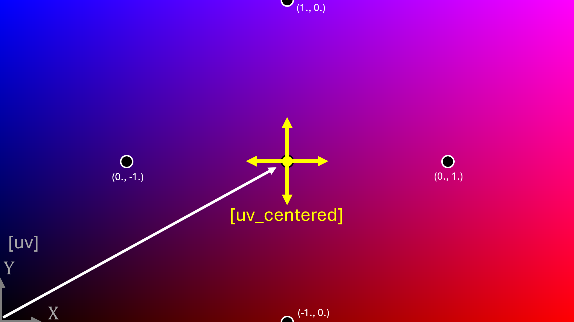
Figure 3: Centered basis coordinate system.
4) Function to generate a spiral.
We can draw a diagonal line in an U,V cartesian coordinate system by coloring pixels where U=V. Similarly, we can draw a spiral line in an r, $\theta$ polar coordinate system by coloring pixels where r= $\theta$ (Wiki link for those not familiar with polar coordinates).
I’ve created a function called spiralWave() to draw the spiral, with lines drawn as the positive portion of a sin(). After converting the U,V coordinates to r, $\theta$, we can draw a set of shrinking circles in circles_zoom over time (try this in The Force. Adding the $\theta$ coordinate shifts the circles into spirals. The output of the function (0. to 1. values across the coordinate system) is then assigned to the R,G,B channels of the fragment shader output.
1
2
3
4
5
6
7
8
9
10
11
12
13
14
15
16
17
18
19
20
21
22
23
24
25
26
27
28
29
30
31
32
33
34
35
36
37
38
39
40
41
42
// Default Shader Inputs //
// more info: https://thebookofshaders.com/03/

// uniform float    time;               // shader playback time (in seconds)

// Defined Variable Constants
float goldenRatio = 0.618;
float spiral_width = 20.;
float zoom_speed = 2.;
float num_spirals = 3.;
float decay = .99;

// Function: Generate Spiral
float spiralWave(vec2 uv_centered, float curve_ratio, float rate, float num_spirals) {

    // Calculate polar coordinates of centered UV space (r, theta)
    float r = length(uv_centered);
    float theta = atan(uv_centered.x,uv_centered.y);

    // Generate circle, and add theta to offset into spirals
    float circles = r;
    float circles_zoom = sin(r*1. + time); // sin(r*10 + time);
    float spiral_zoom  = sin(r*10. + theta*0.05 + time); // sin(r*10. + theta + time)
    float n_spirals    = sin(r*10. + theta * num_spirals + time);

    return n_spirals;
}

// use the function in our main output
void main () {
    // Normalized pixel coordinates to basis vectors: x,y -> u,v (from 0. to 1.)
    vec2 uv = (gl_FragCoord.xy / resolution.xy);
    // Create new UV, centered at the screen center, for polar coordinates.
    vec2 square_aspect_ratio = resolution.xy/resolution.x;
    vec2 uv_centered = (2.*uv - 1.) * square_aspect_ratio;

    // Create sin spiral
    float gray_spiral = spiralWave(uv_centered, goldenRatio, zoom_speed, num_spirals);

    // Output to screen
	gl_FragColor = vec4(vec3(gray_spiral), 1.);
}
GIF 4: A spiral function. View the Shadertoy code here.
5) Aesthetic Golden Ratio spiral.
To make the spiral pattern more ‘hypnotizing’, I modified the spiral code above to follow paths similar to that of the golden ratio curve. The reason why log(r) shows up is explained on Wiki.
1
2
3
4
5
6
7
8
9
10
11
12
13
14
15
16
17
18
19
20
21
22
23
24
25
26
// Function: Generate Golden Spiral
float spiralWave(vec2 uv_centered, float curve_ratio, float rate, float num_spirals) {

    // Calculate polar coordinates of centered UV space (r, theta)
    float r = length(uv_centered);
    float theta = atan(uv_centered.x,uv_centered.y);

    // Modifying curve rate to be a golden ratio
    float golden_ratio_spiral = log(r)/curve_ratio + theta;
    float one_golden_ratio_spiral = sin( golden_ratio_spiral + time);
    float n_golden_ratio_spiral = sin( golden_ratio_spiral * num_spirals + time);

    return n_golden_ratio_spiral;
}

// use the function in our main output
void main () {
    // Normalized pixel coordinates to basis vectors: x,y -> u,v (from 0. to 1.)
    // Create new UV, centered at the screen center, for polar coordinates.
    ...
    // Create sin spiral
    float gray_spiral = spiralWave(uv_centered, goldenRatio, zoom_speed, num_spirals);

    // Output to screen
	gl_FragColor = vec4(vec3(gray_spiral), 1.);
}
GIF 5: Golden ratio spiral function. View the Shadertoy code here.
6) Add spiral pattern eye candy.
Let’s use three steps to add some eye candy.
1) Oversaturate the sin()-generated line to get sharp edges. We can only see pixel intensities from 0. to 1., so scaling the sin to a -50. to 50. range will clip all values above 1. .
2) Invert half of the spiral output, changing the $\theta$ slicing angle with time.
3) Use the fract() function to take the fractional value of the oversaturated sin()*50. to see contours of values that were above 1. . fract() is explained further in The Book of Shaders.
1
2
3
4
5
6
7
8
9
10
11
12
13
14
15
16
17
18
19
20
21
22
23
24
25
// Function: Generate Golden Spiral

void main () {
    // Normalized pixel coordinates to basis vectors: x,y -> u,v (from 0. to 1.)
    // Create new UV, centered at the screen center, for polar coordinates.
    ...
    // Create sin spiral
    float gray_spiral = spiralWave(uv_centered, goldenRatio, zoom_speed, num_spirals);
    // Over saturate values beyond 0:1 for clipping / threshold effect.
    float gray_spiral_clipped = (-50. + spiral_width) + 50. * gray_spiral;

    // Invert half of the spiral
    float invert_rotate = 0.25*time;
    float gray_spiral_split = gray_spiral*sin( sin(invert_rotate)*uv_centered.y + cos(invert_rotate)*uv_centered.x);

    // Invert half of the spiral again, but in the opposite direction
    float gray_spiral_rotate = gray_spiral_split*(sin( cos(invert_rotate+0.5)*uv_centered.y + sin(invert_rotate+0.5)*uv_centered.x)*20.);

    // Apply fractional value function, fract()
    float gray_spiral_fract = fract(gray_spiral_rotate);
    vec4 rbga_spiral_fract = vec4(vec3(gray_spiral_fract),1.0);

    // Output to screen
	gl_FragColor = rbga_spiral_fract;
}
GIF 6: Spiral with fract() applied. View the Shadertoy code here.
7) Video feedback - linear translation.
Feedback delay is achieved by saving the previous rendered frame and mixing it with the current frame. Fortunately, the previous frame is easily accessible in The Force by a pre-defined function texture2D(backbuffer, uv), where the backbuffer is mapped to a U,V coordinate system. In Shadertoy and Max/MSP, however, one often has to get the previous frame using a second ‘buffer’ shader. See the Shadertoy implementation code for an example.
To start simple, the coordinate system of the previous frame is diagonally offset by creating a new transformed U,V.
For clarity, I’ve only applied the feedback on the right side of the shader, where uv.x >= 0.5, using an if statement.
This split view is a helpful trick for understanding and debugging any visual code.
1
2
3
4
5
6
7
8
9
10
11
12
13
14
15
16
17
18
19
20
21
22
23
24
25
26
27
28
29
30
31
// Function: Generate Golden Spiral

void main () {
    // Normalized pixel coordinates to basis vectors: x,y -> u,v (from 0. to 1.)
    // Create new UV, centered at the screen center, for polar coordinates.
    // Create sin spiral
    // Over saturate values beyond 0:1 for clipping / threshold effect.
    // Invert half of the spiral
    // Invert half of the spiral again, but in the opposite direction
    // Apply fract(), get 'vec4 rbga_spiral_fract'.

    // Apply linear displacement to the 'uv' coordinate system
    vec2 uv_transform = uv + vec2(-0.01, 0.0025);
    // Get the previously rendered frame into the current buffer.
    // In Shadertoy, iChannel0 = backbuffer
    vec4 buffer_frame = texture2D(backbuffer, uv_transform);

    // average the previous frame with current frame
    float mix_amount = 0.1;
    vec4 rbga_feedback = mix(buffer_frame, rbga_spiral_fract, mix_amount);

    // Split the rendering screen per effect layer
    vec4 rgba_mode_layer; // empty vec4
    if(uv.x < 0.5)
        rgba_mode_layer = rbga_spiral_fract;
    else if(uv.x >= 0.5)
        rgba_mode_layer = rbga_feedback;

    // Output to screen
	gl_FragColor = rgba_mode_layer;
}
GIF 7: Linear frame feedback. View the Shadertoy code here.
8) Video feedback - centered rotation.
To make things more ‘hypnotizing’, I wanted the feedback to also rotate. Thanks to linear algebra, our basis vectors can be rotated to any angle by applying a rotation matrix, defined below as mat2 rotate(float angle) (3Blue1Brown has a wonderful video explaining and visualizing basis vector transformations).
There is one problem though: the rotation matrix assumes the basis vectors are at the default bottom left origin, not the center of the screen. While this can be corrected within the matrix, one simple solution is to temporarily move our centered shader back to the corner origin, apply the rotation transform, and then re-center the shader. (There may be a more elegant solution to this, let me know if so!)
1
2
3
4
5
6
7
8
9
10
11
12
13
14
15
16
17
18
19
20
21
22
23
24
25
26
27
28
29
30
31
32
33
34
35
36
37
38
39
40
41
42
// Function: Generate Golden Spiral

// Function: Rotation Matrix. https://en.wikipedia.org/wiki/Rotation_matrix
mat2 rotate(float angle) {

    return mat2(
        cos(angle), -sin(angle),
        sin(angle), cos(angle)
    );
}

void main () {
    // Normalized pixel coordinates to basis vectors: x,y -> u,v (from 0. to 1.)
    // Create new UV, centered at the screen center, for polar coordinates.
    // Create sin spiral
    // Over saturate values beyond 0:1 for clipping / threshold effect.
    // Invert half of the spiral
    // Invert half of the spiral again, but in the opposite direction
    // Apply fract(), get 'vec4 rbga_spiral_fract'.

    // Rotate the 'uv' coordinate system about the center of the screen.
    vec2 uv_transform = uv - vec2(0.5);
    uv_transform = uv_transform*rotate(0.05);
    uv_transform = uv_transform + vec2(0.5);
    // Get the previously rendered frame into the current buffer.
    // In Shadertoy, iChannel0 = backbuffer
    vec4 buffer_frame = texture2D(backbuffer, uv_transform);

    // average the previous frame with current frame
    float mix_amount = 0.1;
    vec4 rbga_feedback = mix(buffer_frame, rbga_spiral_fract, mix_amount);

    // Split the rendering screen per effect layer
    vec4 rgba_mode_layer; // empty vec4
    if(uv.x < 0.5)
        rgba_mode_layer = rbga_spiral_fract;
    else if(uv.x >= 0.5)
        rgba_mode_layer = rbga_feedback;

    // Output to screen
	gl_FragColor = rgba_mode_layer;
}
GIF 8: Rotational frame feedback. View the Shadertoy code here.
9) Delay eye-candy and fun functions.
At this stage of shader development, it’s ok to experiment by the trial and error of different function combinations to see what yields interesting results. To add another level of eye candy, I added 2 more steps:
Slightly shift the color of every delayed frame buffer.
Experiment with combinations of functions (
max()andfract()in my case) to find pretty patterns.
1
2
3
4
5
6
7
8
9
10
11
12
13
14
15
16
17
18
19
20
21
22
23
24
25
26
27
28
29
// Function: Generate Golden Spiral
// Function: Rotation Matrix. https://en.wikipedia.org/wiki/Rotation_matrix

void main () {
    // Normalized pixel coordinates to vectors: x,y -> u,v (from 0. to 1.)
    // Create new UV, centered at the screen center, for polar coordinates.
    // Create sin spiral
    // Over saturate values beyond 0:1 for clipping / threshold effect.
    // Invert half of the spiral
    // Invert half of the spiral again, but in the opposite direction
    // Apply fract(), get 'vec4 rbga_spiral_fract'.
    // Rotate the 'uv' coordinate system about the center of the screen.

    // Get the previously rendered frame into the current buffer.
    // In Shadertoy, iChannel0 = backbuffer
    vec4 buffer_frame = texture2D(backbuffer, uv_transform);
    // add slight color shift per buffer
    buffer_frame = (buffer_frame - vec4(0.0, 0.01, 0.05, 1.0)) * decay;

    // average the previous frame with current frame
    float mix_amount = 0.1;
    vec4 rbga_feedback = mix(buffer_frame, rbga_spiral_fract, mix_amount);

    // fun fract() effect
    vec4 rbga_feedback_fract = fract(max(fract(rbga_feedback*1.02), 1.-rbga_spiral_fract)*1.1);

    // Output to screen
	gl_FragColor = rbga_feedback_fract;
}
With that, the shader is complete. As a bonus step, we can add mouse interactivity by adding float mouse_pos_x = mouse.x/resolution.x;, and adjusting a parameter such as the rotation speed, frame delay mixing intensity, or the position of which layers get displayed. The full code (written for The Force) is below in the Appendix.
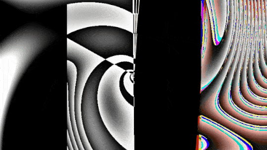
GIF 9: Additional effects. View the Shadertoy code for the mouse interactivity, here.
How are GLSL shaders used in practice?
In addition to being fun to look at, what purpose can this spiral shader serve for a performing artist? Here is how I used part of this shader in my mainstage visuals at MAGFest Super 2025 with AmateurLSDJ (Tyrese).
I wanted to create a unique visual theme for every song in Tyrese’s set. One song was called Golden Ratio, and I had the golden ratio spiral stuck in my head. A pre-rendered video of a spiral asset was not an option as all my live visuals are audio-reactive and I like tweaking pattern details on stage. Once a GLSL shader is made, it can run within Max/MSP using a jit.gl.slab @file Golden-Ratio.jxs block and accept external ‘param’ variables. Note that pure GLSL or shadertoy code requires some minor translation to run Max and other software. See Federico Foderaro’s video for guidance.
In addition to live rendering, 2D GLSL codes are efficient enough to run multiple of the same shader in parallel on a laptop GPU. So, I added a 2D physics engine in my Max/MSP patch, where every ‘ball’ was a mini spiral shader plane. For simplicity, each ‘ball’ had the same shader input and slight transformations on the ‘ball’ planes themselves. While I only fully controlled two GLSL shaders in parallel, in theory one could have a unique shader for every ‘ball’. The bottleneck then becomes managing variables in your higher-level visual software, not the compute time.
With some jit.gl.pix effects layered on top (which is just node-code GLSL), this is how it turned out!
(skip to 14:20)
Concluding remarks.
I learned a lot more about GLSL by writing and explaining my code in this tutorial. I am no GLSL expert, so there may be errors in some of my explanations. If you have more experience and spot an opportunity to improve this page, please let me know and I will revise!
Take care and look out for each other <3
- pip :P
Appendix A: Full Shader Code.
1
2
3
4
5
6
7
8
9
10
11
12
13
14
15
16
17
18
19
20
21
22
23
24
25
26
27
28
29
30
31
32
33
34
35
36
37
38
39
40
41
42
43
44
45
46
47
48
49
50
51
52
53
54
55
56
57
58
59
60
61
62
63
64
65
66
67
68
69
70
71
72
73
74
75
76
77
78
79
80
81
82
83
84
85
86
87
88
89
90
91
92
93
94
95
96
97
98
99
100
101
102
103
104
105
106
107
108
109
110
111
112
113
114
115
116
// Mini Lecture - A GLSL Tutorial in Practice //
// Plasma Pip   - 2025 //

// Shader Inputs (on by default) //
// more info: https://thebookofshaders.com/03/

// uniform vec3     gl_FragCoord;       // window coordinates of fragment shader (x,y,z)
// uniform vec2     resolution;         // viewport resolution (in pixels)
// uniform float    time;               // shader playback time (in seconds)
// uniform vec4     mouse;              // mouse X,Y coordinate, mouse click X,Y coordinate

// Defined Variables
float goldenRatio = 0.618;
float spiral_width = 20.;
float zoom_speed = 2.;
float num_spirals = 3.;
float decay = .99;

// Function: Generate Spiral
float spiralWave(vec2 uv_centered, float curve_ratio, float rate, float num_spirals) {

    // Calculate polar coordinates of centered UV space (r, theta). https://en.wikipedia.org/wiki/Polar_coordinate_system
    float r = length(uv_centered);
    float theta = atan(uv_centered.x,uv_centered.y);

    // Generate circle, and add theta to offset into spirals
    float circles = r;
    float circles_zoom = sin(r*1. + time); // sin(r*10 + time);
    float spiral_zoom  = sin(r*10. + theta*0.05 + time); // sin(r*10. + theta + time)
    float n_spirals    = sin(r*10. + theta * num_spirals + time);

    // Modifying curve rate to be a golden ratio. https://en.wikipedia.org/wiki/Golden_spiral
    float golden_ratio_spiral = log(r)/curve_ratio + theta;
    float one_golden_ratio_spiral = sin( golden_ratio_spiral + time);
    float n_golden_ratio_spiral = sin( golden_ratio_spiral * num_spirals + time);

    return n_golden_ratio_spiral;
}

// Function: Rotation Matrix. https://en.wikipedia.org/wiki/Rotation_matrix
mat2 rotate(float angle) {

    return mat2(
        cos(angle), -sin(angle),
        sin(angle), cos(angle)
    );
}

void main () {

    // Interactive inputs
    float mouse_pos_x = mouse.x/resolution.x;
    float mouse_pos_y = mouse.y/resolution.y;

    // Normalized pixel coordinates to basis vectors: x,y -> u,v (from 0. to 1.)
    vec2 uv = (gl_FragCoord.xy / resolution.xy);

    // Generate spiral pattern
    // Create new UV, centered at the screen center, for polar coordinates.
    vec2 square_aspect_ratio = resolution.xy/resolution.x;
    vec2 uv_centered = (2.*uv - 1.) * square_aspect_ratio;

    // Create sin spiral
    float gray_spiral = spiralWave(uv_centered, goldenRatio, zoom_speed, num_spirals);
    // Over saturate values beyond 0:1 for clipping / threshold effect.
    float gray_spiral_clipped = (-50. + spiral_width) + 50. * gray_spiral;
    // Invert half of the spiral
    float invert_rotate = 0.25*time;
    float gray_spiral_split = gray_spiral*sin( sin(invert_rotate)*uv_centered.y + cos(invert_rotate)*uv_centered.x);
    // Invert half of the spiral again, but in the opposite direction
    float gray_spiral_rotate = gray_spiral_split*(sin( cos(invert_rotate+0.5)*uv_centered.y + sin(invert_rotate+0.5)*uv_centered.x)*20.);
    // Apply fractional value function, fract()
    float gray_spiral_fract = fract(gray_spiral_rotate);
    vec4 rbga_spiral_fract = vec4(vec3(gray_spiral_fract),1.0);

    // FEEDBACK!

    // Linear displacement
    //vec2 uv_transform = uv + vec2(0.01, 0.000);
    // Rotate coordinate system, about the center of the screen.
    vec2 uv_transform = uv - vec2(0.5);       // 2
    uv_transform = uv_transform*rotate(0.05*mouse_pos_y);   // 1 // uv_transform*rotate(0.05*mouse_pos_y)
    uv_transform = uv_transform + vec2(0.5);  // 3

    vec4 buffer_frame = (texture2D(backbuffer, uv_transform) - vec4(0.0, 0.01, 0.05, 1.0)) * decay; // adding slight color shift per buffer

    // average the previous frame with current frame
    vec4 rbga_feedback = mix(buffer_frame, rbga_spiral_fract, 0.01);

    // fun fract
    vec4 rbga_feedback_fract = fract(max(fract(rbga_feedback*1.02), 1.-rbga_spiral_fract)*1.1);


    // Interactive mode switcher
    float slider = mouse_pos_x*4.;

    vec4 frag_rgba_slider; // empty vec4

    if(uv.x < 0.25*slider)
        frag_rgba_slider = vec4(vec3(gray_spiral_rotate),1.0);
    else if(uv.x < 0.5*slider)
        frag_rgba_slider = rbga_spiral_fract;
    else if(uv.x < 0.75*slider)
        frag_rgba_slider = buffer_frame;
    else
        frag_rgba_slider = rbga_feedback_fract;

	// Output to screen
	gl_FragColor = frag_rgba_slider;

}

// Shader Outputs //

// uniform vec4     gl_FragColor;       // color of fragment shader [R, G, B, A]
// uniform vec4     backbuffer;         // Stores gl_FragColor from previous frame
The exact code and files within this web page are licensed under a CC BY-NC-SA 4.0 Attribution-NonCommercial-ShareAlike International license. (AKA: Make it your own before calling it your own)
Appendix B: Footnotes.
I have not run GLSL on Raspberry Pis myself, but here are the resources I am aware of: 1) Antonin Stefanutti wrote a guide on Running GLSL on DRM/KMS Linux kernel subsystems. 2) Andrei Jay creates and sells pre-formatted Raspberry Pi synths called ‘VSERPI’, with open source code. ↩︎
Shout out to Char Stiles for introducing me to The Force during her GLSL workshop at The Frank-Ratchye STUDIO for Creative Inquiry at CMU. She was an inspiration for making this tutorial. Check out her work! ↩︎